Programming display and input devices for the QEMU Versatile board
The QEMU Versatile emulates the Versatile System on Chip. The board comes with a fairly complete set of devices such as a display controller, keyboard, mouse, ethernet, and other miscellaneous devices providing the ability to run a complete OS such as Linux on top.
This tutorial will show how to program the display and input devices and use it without an OS. We use QEMU 2.9.0 for this tutorial and the Plan 9 toolchain. This is only a barebones example that gets it working, for a more complete setup, refer to the documentation of the devices.
Note: This example only works in QEMU, it will not work on a real board because we skip some setup that real hardware would need but QEMU doesn’t.
We setup the board as described in the previous article without the MMU to make things more expedient. We disable all interrupts and initialize the devices and then jump into main() to do all the setup of the devices and main loop.
// l.s
#define SVC_MODE 0x13
#define NO_INT 0xc0

// start execution here
TEXT _start(SB), 1, $-4
	// supervisor mode and no interrupt
	MOVW $(SVC_MODE|NO_INT), R1
	MOVW R1, CPSR

	// setup R12 for global variable access
	MOVW $setR12(SB), R12

	// setup stack and jump to C
	MOVW $0x8000, SP
	BL main(SB)

	// loop forever
	B 0(PC)
// main.c
#include "u.h"
#include "libc.h"
#include "dat.h"
#include "fns.h"
// cursor on the screen
Cursor cursor = {
.w = 15,
.h = 15,
};
// our screen
Clcd *screen;
// the artwork we are drawing
Texture pic;
// setup the texture attribute
// for rendering
static void
artinit(void)
{
extern u32 art[];
Texture *t;
t = &pic;
t->p = art;
t->w = 190;
t->h = 222;
}
// get keyboard and mouse events
static void
event(void)
{
u32 kb, ms;
for (;;) {
pollinput(&kb, &ms);
if (kb == 0 && ms == 0)
break;
updatecursor(&cursor, ms);
if (kb)
print("key %x\n", kb);
}
}
static void
draw(void)
{
Rect r;
// disable the screen so we can draw to it
// if we enable the screen while drawing, it can cause
// the update to show partial updates, where as we want
// something like double buffering, this achieves something
// like double-buffering
clcddisable(screen);
// clear to a gray background
fillrect(0, 0, screen->w, screen->h, 0xff555555);
// draw a image at the center of the screen
r = (Rect){(screen->w - pic.w) / 2, (screen->h - pic.h) / 2, pic.w, pic.h};
filltexture(&pic, &r, nil);
// draw our cursor
fillrect(cursor.x, cursor.y, cursor.w, cursor.h, 0xff00ff00);
// draw the device, we need to delay a little so QEMU can have a chance to refresh
// if we do not have a delay, QEMU can get into a execution path where it only
// sees the disable and not the enable when it decides to refresh, thus giving
// us a black screen.
clcdenable(screen);
delay(5);
}
void
main(void)
{
// setup UART for printing to terminal
uartinit();
// setup timer so we can sleep
timerinit();
// setup the display so we can draw to the screen
clcdinit();
// setup keyboard and mouse
inputinit();
// setup texture for drawing
artinit();
// game style loop
for (;;) {
event();
draw();
}
}In main, we setup all of the devices first and then go into a loop. UART is setup first because we want to be able to print to stdio as quickly as possible for debugging purposes. The timer is setup next in order to implement delays which the display device needs. We then initialize they keyboard and mouse and load the artwork at the end. We do not enable interrupts here as we will handle all the device updates using polling mode.
The main loop consists of handling keyboard/mouse events and drawing to the screen the artwork that we loaded. The artwork we loaded is a 32 bit RGBA encoded buffer that we just passed directly to the frame buffer for rendering.
We are now ready to cover how to map the memory of the devices and program them.
Memory Map
We can get the memory map of where the device lives in the QEMU Versatile source code. These addresses are physical mappings and we can just make a pointer to the location and start using it.
Here are the full memory mapping of the Versatile:
Memory map for Versatile:

0x10000000 System registers.
0x10001000 PCI controller config registers.
0x10002000 Serial bus interface.
0x10003000 Secondary interrupt controller.
0x10004000 AACI (audio).
0x10005000 MMCI0.
0x10006000 KMI0 (keyboard).
0x10007000 KMI1 (mouse).
0x10008000 Character LCD Interface.
0x10009000 UART3.
0x1000a000 Smart card 1.
0x1000b000 MMCI1.
0x10010000 Ethernet.
0x10020000 USB.
0x10100000 SSMC.
0x10110000 MPMC.
0x10120000 CLCD Controller.
0x10130000 DMA Controller.
0x10140000 Vectored interrupt controller.
0x101d0000 AHB Monitor Interface.
0x101e0000 System Controller.
0x101e1000 Watchdog Interface.
0x101e2000 Timer 0/1.
0x101e3000 Timer 2/3.
0x101e4000 GPIO port 0.
0x101e5000 GPIO port 1.
0x101e6000 GPIO port 2.
0x101e7000 GPIO port 3.
0x101e8000 RTC.
0x101f0000 Smart card 0.
0x101f1000 UART0.
0x101f2000 UART1.
0x101f3000 UART2.
0x101f4000 SSPI.
0x34000000 NOR Flash
We will only use UART, CLCD controller, timer, keyboard, and mouse. We will end up only using these memory spaces:
Memory map that we will use:

0x10006000 KMI0 (keyboard).
0x10007000 KMI1 (mouse).
0x10009000 UART3.
0x10120000 CLCD Controller.
0x101e2000 Timer 0/1.
0x101e3000 Timer 2/3.
0x101f1000 UART0.
0x101f2000 UART1.
0x101f3000 UART2.
Since we are operating without an MMU, we can just create a pointer to these addresses and write to it directly.
UART
UART provides serial output which we route to stdio using the QEMU command line flag -serial stdio. Only the DATA register is used for outputting to UART for printing to stdout.
To use the UART DATA register, we just need to write to the register the character we want to output, QEMU should then print it out to standard output. We only use UART0 for terminal output, so the other UARTs are left unused, but using those would be the same code; just at different register offsets. Here is the link to the UART data sheet.
// uart.c

#include "u.h"
#include "libc.h"
#include "dat.h"

// UART base addresses
enum {
	UART0 = 0x101f1000,
	UART1 = 0x101f2000,
	UART2 = 0x101f3000,
	UART3 = 0x10009000,
};

// register offsets, 32 bit wide
enum {
	// DATA register for writing output characters
	DR = 0x0,
};

// physical UART device descriptions
Uart physuart[] = {
    {
        .r = (void *)UART0,
    },
    {
        .r = (void *)UART1,
    },
    {
        .r = (void *)UART2,
    },
    {
        .r = (void *)UART3,
    },
};

// initializes UART
void
uartinit(void)
{
	// use UART0 for the console output
	consuart = &physuart[0];
}

// output a character to UART
void
uartputc(Uart *u, int c)
{
	u->r[DR] = c;
}
Timer
The timers contain a monotonic counter that ticks with a fixed period, enabling us to keep track of elapsed time. We use it to implement delays for the CLCD display controller for refreshing the screen. Since we only need to sleep in a single threaded context, only one timer is needed. We setup the timer to be 32 bit resolution and enable it for the first timer. By default, the timer ticks at 1 MHZ a second so we just need to read the current value in a loop to get the delay we need. Here is the link to the Timer data sheet.
// timer.c

#include "u.h"
#include "libc.h"
#include "dat.h"
#include "fns.h"

// timer registers, 32 bit wide
enum {
	LOAD = 0x0,
	VALUE,
	CTRL,
	INTCLR,
	RIS,
	MIS,
};

// control bits
enum {
	ENABLE = 0x80,
	PERIODIC = 0x40,
	INTENABLE = 0x20,
	RESLN32 = 0x2,
	ONESHOT = 0x1,
};

Timer phystimer[4] = {
    {
        .r = (void *)0x101e2000,
    },
    {
        .r = (void *)(0x101e2000 + 0x20),
    },
    {
        .r = (void *)0x101e3000,
    },
    {
        .r = (void *)(0x101e3000 + 0x20),
    },
};

// reset the timer
static void
reset(Timer *t)
{
	// enable the device with 32 bit counter wide
	t->r[CTRL] = ENABLE | RESLN32;
}

// initializes the timer
void
timerinit(void)
{
	reset(&phystimer[0]);
}

// delay for n milliseconds
void
delay(int n)
{
	while (--n >= 0)
		microdelay(1000);
}

// delay for n microseconds
void
microdelay(int n)
{
	Timer *t;
	u32 a, b;

	// we do not need to worry about underflow here
	// since the unsignedness of the values ensure
	// that the wrap around calculation is still right
	t = &phystimer[0];
	a = t->r[VALUE];
	while (a - t->r[VALUE] < n + 1)
		;
}
CLCD
CLCD provides us with a frame buffer display that we can draw to. We setup the mode to be 32 bit true color 640x480 resolution. We also provide a free memory area for the framebuffer. We also need to enable and disable the display during drawing so we do not see the partial updates which shows tearing. The frame buffer is used as a building block for the familiar
setpixel and fillrect. The only thing we need to do is write to the frame buffer and enable the device to see the update. Here is the CLCD data sheet.
// clcd.c

#include "u.h"
#include "libc.h"
#include "dat.h"
#include "fns.h"

// base physical address
// of the CLCD device
enum {
	CLCD = 0x10120000,
};

// the registers offset
// each is 32 bit wide
enum {
	TIM0 = 0x0,
	TIM1 = 0x1,
	TIM2 = 0x2,
	TIM3 = 0x3,
	UPBASE = 0x4,
	LPBASE = 0x5,
	CTRL = 0x6,
	IMSC = 0x7,
	ICR = 0xa,
	SYS = 0x14,
	PAL = 0x80,
};

// system register bits
enum {
	PWR3V5 = 0x10,
	LCDIOON = 0x4,
};

// control register bits
enum {
	CR_EN = 0x1,
	CR_BGR = 0x100,
	CR_BEBO = 0x200,
	CR_BEPO = 0x400,
	CR_PWR = 0x800,
};

// color depth
enum {
	BPP1 = 0,
	BPP2,
	BPP4,
	BPP8,
	BPP16,
	BPP32,
	BPP16_565,
	BPP12,
};

Clcd physclcd[] = {
    {
        .r = (void *)CLCD,
        .w = 640,
        .h = 480,
        .fb = (void *)0x150000,
    },
};

// resets the CLCD controller
static void
reset(Clcd *c)
{
	// turn on the device
	c->r[SYS] = PWR3V5 | LCDIOON;

	// setup width/height
	c->r[TIM0] = c->w / 4 - 4;
	c->r[TIM1] = c->h - 1;

	// frame buffer location
	c->r[UPBASE] = (uintptr)c->fb;

	// 32 bit color (rgba)
	c->r[CTRL] = (BPP32 << 1);
}

// disable the screen, it leaves whatever was on
// the screen intact
void
clcddisable(Clcd *c)
{
	c->r[CTRL] &= ~(CR_PWR | CR_EN);
}

// enable the screen, QEMU will start updating
// the frame buffer again
void
clcdenable(Clcd *c)
{
	c->r[CTRL] |= (CR_PWR | CR_EN);
}

// initializes the CLCD display controller
void
clcdinit(void)
{
	reset(&physclcd[0]);
	screen = &physclcd[0];
	fillrect(0, 0, screen->w, screen->h, 0xff555555);
	microdelay(5);
}
Keyboard/Mouse
Keyboard/Mouse are as you expect. The interface is fairly simple, we just enable the device and read the status register to see if there is data available, if there is just grab the data and parse it. Here is the link to the Input data sheet.
// input.c

#include "u.h"
#include "libc.h"
#include "dat.h"
#include "fns.h"

// registers, 32 bit wide
enum {
	CTRL = 0,
	STAT,
	DATA,
	CLKDIV,
	IR,
};

// control register bits
enum {
	ENABLE = 0x4,
};

// status register bits
enum {
	RXFULL = 0x10,
};

static Input physinput[] = {
    {
        .r = (void *)0x10006000,
    },
    {
        .r = (void *)0x10007000,
        .ismouse = true,
    },
};

// send data and drain input
static void
send(Input *p, u32 v)
{
	p->r[DATA] = v;
	while (p->r[STAT] & RXFULL)
		v = p->r[DATA];
}

// reset the device
static void
reset(Input *p)
{
	p->r[CTRL] = ENABLE;

	// this enable the ps2 interface for usage
	// without this we won't get the mouse events
	if (p->ismouse)
		send(p, 0xf4);
}

// initializes the input
void
inputinit(void)
{
	reset(&physinput[0]);
	reset(&physinput[1]);
}

// polls for input if there is no input
// set events to 0
void
pollinput(u32 *kb, u32 *ms)
{
	Input *p;
	int i;

	*kb = *ms = 0;
	for (i = 0; i < nelem(physinput); i++) {
		p = &physinput[i];
		if (!(p->r[STAT] & RXFULL))
			continue;

		if (i == 0) {
			// keyboard just gets raw data
			// ignore 0xf0, that is a "end marker"
			*kb = p->r[DATA];
			if (*kb == 0xf0)
				*kb = 0;
		} else {
			// mouse gets 3 packet, the
			// status, dx, dy
			*ms |= p->r[DATA];
			*ms |= (p->r[DATA] << 8);
			*ms |= (p->r[DATA] << 16);
		}
	}
}

// move the cursor based on the mouse movement
void
updatecursor(Cursor *c, u32 ms)
{
	// move x and y, the mouse events
	// switches the y coordinates around
	c->dx = (s8)((ms >> 8) & 0xff);
	c->dy = -(s8)((ms >> 16) & 0xff);
	c->x += c->dx;
	c->y += c->dy;

	// bounds checking so the cursor does
	// not get out of the screen
	if (c->x < 0)
		c->x = 0;
	if (c->x + c->w >= screen->w)
		c->x = screen->w - c->w;

	if (c->y < 0)
		c->y = 0;
	if (c->y + c->h >= screen->h)
		c->y = screen->h - c->h;
}
Odds and Ends
For some of our libc functions such as print, we have to use va_args and division for printing integers. This requires us
to pull in some code from the Plan 9 libc functions.
For va_list, we can get the code for it from u.h from the Plan 9 source tree. The Plan 9 compilers passes the variadic variables on the stack, so we just start walking memory locations from an argument to get to the next one.
Division is done in software as some ARM processors do not have division support, so we need pull the code from the Plan 9 libc functions (vlrt.c, vlop.s, and div.s specifically). If one tries to use the division and modulus operations without these files, the linker will try to pull them in and fail if it can’t find them.
Conclusion
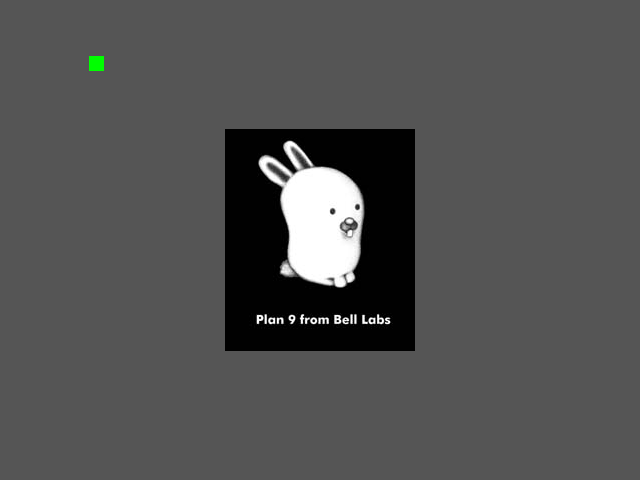
If all goes well, this is what you should see from QEMU:
You can get the code to the demo here.